Hardware Installation Guide
For XVideo700, PowerVideo700, and MultiVideo700 on HP Workstations
Part Number: 917-027379, Rev. F
(C) Copyright Parallax Graphics, Inc. 1997. All rights reserved.
Printed in the U.S.A.
Parallax Graphics, Inc., 2500 Condensa Street, Santa Clara, CA 95051 USA
Phone: 408-727-2220; Fax: 408-727-2367
E-mail: sales@parallax.com or tsupport@parallax.com
World Wide Web: http://www.parallax.com
No part of this manual or the accompanying software may be reproduced or transmitted in any form or by any means--electronic or mechanical, including photocopying and recording--without the prior written permission of Parallax Graphics, Inc.
VideoStream, XVideo, XVideo Xtra, PowerVideo, PowerVideo-Play, MultiVideo, Video Development Environment, VideoTool, MovieTool, Real-Time MovieTool, and Parallax Graphics are trademarks or registered trademarks of Parallax Graphics, Inc.
All other products or services mentioned in this document are identified by the trademarks or service marks of their respective companies or organizations, and Parallax Graphics, Inc. disclaims any responsibility for specifying which marks are owned by which companies or organizations.
Table of Contents
Preface
How To Use This Manual
Technical Support Contacts
Introduction
Your Video Card's Capabilities
XVideo700
PowerVideo700
MultiVideo700
System Requirements
Installing the Video Card
J Class Installation
C Class Installation
Model 755 Installation
Model 745 and 747 Installation
Model 735 Installation
Model 725 Installation
Model 715 Installation
Connecting Cables and Devices
Cables for Your Video Card
How to Connect the Cables
Basic Set-Up: Video Input
XVideo700: Video Output
Multiple Video Cards in One System
Powering Up the Workstation
Appendix A: Parallax Video Specifications
General Specifications
Specific Video Overlay Cards
Appendix B: Hardware Warranty and Repairs
Hardware Warranty
If You Need a Repair
Appendix C: FCC and CE Mark Compliance
Preventing Radio Interference: Your Responsibility
Avoiding Penalties in the USA
FCC Class A Notice
Preface
This preface describes how to use this manual and how to reach us if you need technical support. This preface includes:
How To Use This Manual
Font Conventions
Related Documents
Technical Support Contacts
How To Use This Manual
Before you begin using this manual, please read your Release Notes to find out about any recently added instructions.
This Hardware Installation Guide describes your Parallax Graphics video overlay card and cables, and tells you how to install the video overlay card and set up the cables. You can use this manual as an installation guide and a reference.
Font Conventions
Italics Manual titles, new terms being defined.
Typewriter Font Commands typed in an X window, text that would appear in an X window.
Related Documents
Release Notes
Skim before installation, then read in detail. These notes provide important information about recent changes and bugs.
Software Installation Guide
Use for software installation and de-installation.
Multimedia User's Guide
Learn how to use the application software, VideoTool, MovieTool, etc.
Video Development Environment Reference Guide
For developers building custom software applications using digital video: Use as a reference guide in development.
Technical Support Contacts
If you need any technical assistance during installation, please contact:
Parallax Graphics Technical Support:
Phone: +1 703 450 7718
E-mail: tsupport@parallax.com
World Wide Web: http://www.parallax.com
TAC-4 Technical Support
If you are a TAC-4 customer (U.S. Navy TAC-4 program), then you should call the Hewlett-Packard TAC-4 Help Desk for technical support:
Hewlett-Packard TAC-4 Help Desk
Phone: 800-203-TAC4 (800-203-8224)
Fax: 508-436-5167
This chapter briefly describes your Parallax Graphics video overlay card and system requirements. This chapter includes:
Your Video Card's Capabilities
XVideo700
PowerVideo700
MultiVideo700
System Requirements
XVideo700, PowerVideo700, and MultiVideo700 are EISA Bus video overlay cards that display high quality video on your workstation:
- Full motion video
- 30 frames/second NTSC
- 25 frames/second PAL or SECAM
- Full resolution video
- 640x480 pixels (525 line) NTSC
- 768x576 pixels (625 line) PAL or SECAM
- 24-bit TrueColor video
With any Parallax Graphics video card, you can display live video from a video camera, VCR, TV cable, or other analog source. You can also capture still images for monitoring applications such as manufacturing inspection and surveillance. XVideo700, Power-Video700, and MultiVideo700 now support video input from composite and S-VHS (Y/C) format video devices, in NTSC, PAL, and SECAM standards.
On the following pages are brief descriptions of XVideo700, PowerVideo700, and MultiVideo700 cards.
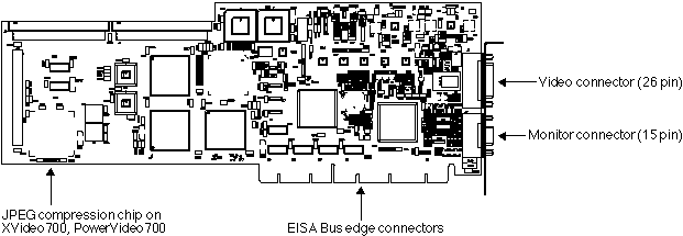
Figure 1-1 Parallax Graphics video overlay card for HP workstations.
With XVideo700's hardware compression, you can capture and compress digital video movies in real-time and play them back locally or over a network from a video-on-demand server. You can send and receive compressed video over a data network in real-time for remote monitoring and videoconferencing applications such as distance learning, collaboration, and telemedicine.
With XVideo700, you can also display live video from two sources simultaneously and send video out from the workstation to a VCR, video projector, or other analog video device for presentations or distribution to a wider audience. At a given moment, you can display live video inputs from two sources simultaneously, or you can display one live video input and send video out to a VCR or other device. Video output can be composite or S-VHS (Y/C) format in NTSC or PAL standards.
The PowerVideo700 card supports one composite or S-VHS (Y/C) video input, and includes hardware compression/decompression. The hardware compression allows you to capture and play back digital video in real time for applications like capturing movies and networked applications like video servers and videoconferencing.
The MultiVideo700 card supports a single composite or S-VHS (Y/C) video input for viewing video in a window and capturing video still images for applications like video monitoring for surveillance and manufacturing inspection.
Before you start installing your EISA Bus video overlay card, please check to make sure you have all of the required hardware, software, etc. for your new video card:
Platform *HP Apollo 9000 Series 700, B, C, and J Classes
EISA Bus Interface One available EISA Bus slot
Operating System HP-UX 9.03, 9.05, 9.07, 10.10, or 10.20
Window Environment HP VUE 2.0 or higher or CDE
Available Disk Space 35 Megabytes (MB) space on a local hard drive
System RAM 64 MB recommended (32 MB minimum)
Swap Space 64 MB recommended (32 MB minimum)
(MultiVideo700 needs just 32 MB recommended)
Framebuffer Types *HCRX 24, Visualize 24, Visualize 48
Monitor Types *1280 x 1024 pixels @ 60-75 Hz
*1024 x 768 pixels @ 60-75 Hz
*NOTE: Not all systems work at all display resolutions. See Release Notes for details on tested systems.
NOTE: The hardware supports displays at 1280 x 1024 or 1024 x 768 pixels at frequencies between 60-75 Hz (theoretically up to 76 Hz). Calibration files support several specific display types (1280 x 1024 @ 72 and 60 Hz, 1024 x 768 @ 75 and 74 Hz), and can be adjusted to meet other frequencies between 60-75 Hz. For details, see your Release Notes and Software Installation Guide instructions for Calibrating and using Calibrate with the ``-hv'' option (Troubleshooting).
For complete specifications, see Appendix A.
When configuring your system for multimedia, it is advisable to contact your multimedia software supplier/s to find out their required disk space and recommended swap space, since some multimedia software requires significant memory and swap space.
This chapter describes how to install your Parallax Graphics video card in your HP workstation. This chapter includes:
J Class Installation
C Class Installation
Model 755 Installation
Model 745 and 747 Installation
Model 735 Installation
Model 725 Installation
Model 715 Installation
- To get up-to-date information about any recent changes, please read the Release Notes before you begin installation.
- We hope that your installation of your video card is easy
and problem-free. If you need any technical help during installation, please contact Parallax Graphics technical support; see Technical Support Contacts for complete contact information).
- To USA and European customers: You are responsible to ensure continued compliance with USA Federal Communi-cations Commission (FCC) and European Community (CE Mark) rules by installing and using this video card and cables as described in the manuals, by using the cables provided,
by not making any changes or modifications to the video card or cables, and in the USA, by using the equipment in a commercial zone. In the USA, if you do not follow these guidelines and your equipment causes disruptive radio interference, you may have to stop using the equipment until you correct the radio interference problem at your own expense. For more information, see Appendix C.
If you are installing more than one Parallax video card in your multi-slot HP workstation (J or C Series, or Model 755, 745, or 725), follow normal installation procedures for each card. See Chapter 3 for special instructions for multiple card cable set-up. Your Software Installation Guide also has special multiple card set-up instructions. Parallax supports up to three Parallax video cards per HP workstation.
XVideo700, PowerVideo700, and MultiVideo700 do not currently work in EISA expansion chassis.
Follow these steps to install the Parallax video card into your J Class workstation.
For more details (such as restrictions on where to put framebuffer cards), see your workstation Owner's Guide.
Save your work and shut down the workstation.
Turn off the power to your system (workstation, monitor, and externals).
Disconnect the cables from your workstation to the monitor, external devices, and network. Disconnect cables attached to installed EISA cards.
Use a grounding strap during installation to protect yourself, your workstation, and your video card from electric shocks and damage. (We ship a grounding strap in your hardware package.)
Attach one end of the grounding strap to your wrist. (With the adhesive side to your skin, wrap the grounding strap firmly around your wrist.)

Connect the other end (the copper end) of the grounding strap to any exposed metal casing on the workstation system unit (such as the power supply casing).
If you have an anti-static floor mat, we recommend standing on
it during installation.
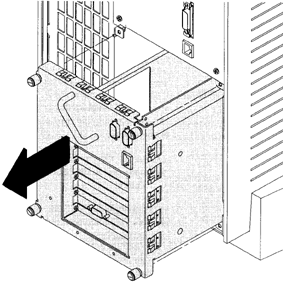
Working from the rear of the workstation, unscrew the four captive screws and pull the EISA Assembly straight out using the handle, as shown below.
Rotate the unit 90 degrees clockwise (onto its side) and place it on a flat surface, as shown below.
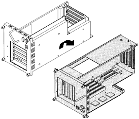
Unscrew one screw at the back of the cover and lift the cover up and out to remove it from the EISA Assembly, as shown below.

Unscrew one screw at the top of the slot cover plate and pull the cover straight up to remove it, as shown below.
Make sure that all unused EISA option slots have a blank cover plate installed and secured with a screw to ensure proper air flow and FCC/Electro-Magnetic Interference emissions compliance.
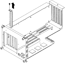
Pick up the Parallax video card, holding it by the edges. Place the Parallax card in the EISA board guides and slide the card gently but firmly into the EISA connector, as shown below. Do not force the card because you might damage the connector pins. Check to make sure the card is evenly inserted and seated properly.
Make sure you are grounded to prevent electrostatic damage to the card. Handle the card only by the edges. Do not touch components on the face of the card.
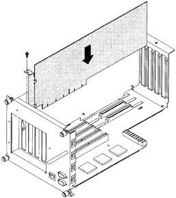
Secure the Parallax card with one screw in the top of the board connector bracket.
Insert the EISA Assembly cover in the guide, and secure it with the screw, as shown below.

Rotate the EISA Assembly unit back 90 degrees, as shown below.

Grasp the EISA Assembly handle, and slide the EISA Assembly back into the system unit, as shown below. Secure it with the four captive screws.
Check to make sure the EISA Assembly and system unit are securely joined and all four captive screws are completely tightened to maintain FCC/Electro-Magnetic Interference compliance.
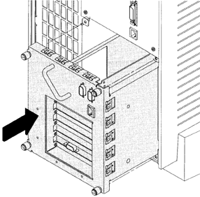
Reconnect the cables from your workstation to the monitor, external devices, and network. Reconnect the cables to other EISA cards. Do not turn the power on yet.
Go to Chapter 3 for instructions on connecting cables to your Parallax video card.
Follow these steps to install the Parallax video card into your C Class workstation.
For more details (such as restrictions on where to put framebuffer cards), see your workstation Owner's Guide.
Save your work and shut down the workstation.
Turn off the power to your system (workstation, monitor, and externals).
Disconnect the cables from your workstation to the monitor, external devices, and network. Disconnect cables attached to installed EISA cards.
Use a grounding strap during installation to protect yourself, your workstation, and your video card from electric shocks and damage. (We ship a grounding strap in your hardware package.)
Attach one end of the grounding strap to your wrist. (With the adhesive side to your skin, wrap the grounding strap firmly around your wrist.)

Connect the other end (the copper end) of the grounding strap to any exposed metal casing on the workstation system unit (such as the power supply casing).
If you have an anti-static floor mat, we recommend standing on
it during installation.
Completely loosen the four captive screws on the rear of the system unit, as shown below.
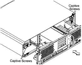
Place one hand on the top of the system unit and push, while pulling the handle on the rear panel with your other hand.
Slide the main tray assembly out of the chassis.
Press the fan release clip and rotate the fan, as shown below.
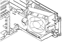
Slide the EISA slider to the side to remove it, as shown below.
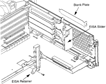
Remove the screw from the EISA retainer, and remove the EISA retainer, as shown above.
Remove the blank plate from the slot in which you wish to install the Parallax video card, as shown above.
Make sure that all unused EISA option slots have a blank cover plate installed and secured to ensure proper air flow and FCC/Electro-Magnetic Interference emissions compliance.
Pick up the Parallax video card, holding it by the edges. Slide the card into the slot, as shown below. Make sure that the hole in the board's handle aligns with the pin in the system's back panel.
Make sure you are grounded to prevent electrostatic damage to the card. Handle the card only by the edges. Do not touch components on the face of the card.
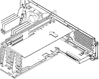
Press in gently but firmly on both ends of the Parallax video card at the same time to make sure that it is firmly seated in the backplane connector. Do not force the card because you might damage the connector pins. Check to make sure the card is evenly inserted and seated properly.
Re-install the EISA retainer and screw in its screw (see below).
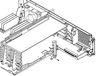
Slide the EISA slider back in place, as shown above.
Rotate the fan back into place, as shown below. Push it into the rear panel firmly until the clip snaps into place.
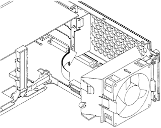
Align the main tray assembly with the chassis and slide the assembly into place, as shown below.
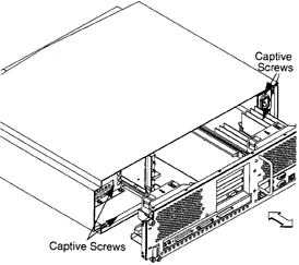
Slide the main tray assembly in until you feel it make contact with the internal connectors.
Push firmly and evenly on the main tray assembly to make sure that all connectors are fully seated.
Tighten the four captive screws.
Check to make sure the main tray is fully seated and all four captive screws are completely tightened to maintain FCC/Electro-Magnetic Interference compliance.
Reconnect the cables from your workstation to the monitor, external devices, and network. Reconnect the cables to other EISA cards. Do not turn the power on yet.
Go to Chapter 3 for instructions on connecting cables to your Parallax video card.
Follow these steps to install the Parallax video card into your Model 755 workstation. For more details, see your HP Owner's Guide.
You should check the total power requirements of all your EISA option cards before installation to make sure you don't exceed the power limitations of EISA option cards on your Model 755. The Parallax video card uses 27.5 Watts or less (27.5 W for XVideo700, 19.0 W for PowerVideo700 or MultiVideo700) For more information, see your Owner's Guide (Installing the EISA Cards).
Save your work and shut down the workstation.
Turn off the power to your system (workstation, monitor, and externals).
Disconnect the cables from your workstation to the monitor, external devices, and network. Disconnect cables attached to installed EISA cards.
Use a grounding strap during installation to protect yourself, your workstation, and your video card from electric shocks and damage. (We ship a grounding strap in your hardware package.)
Attach one end of the grounding strap to your wrist. (With the adhesive side to your skin, wrap the grounding strap firmly around your wrist.)

Connect the other end (the copper end) of the grounding strap to any exposed metal casing on the workstation system unit (such as the power supply casing).
If you have an anti-static floor mat, we recommend standing on
it during installation.
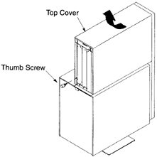
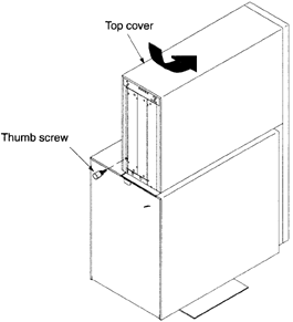
Remove the top cover of the system card cage by removing the thumb screw at the back of the system, and sliding the top cover to the back and pulling it off, as shown below.
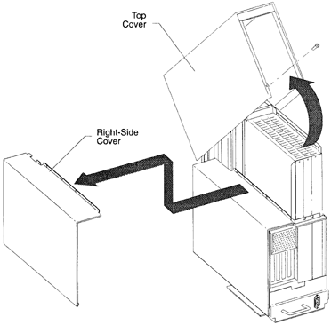
Remove the right-side cover, as shown below.
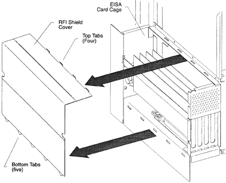
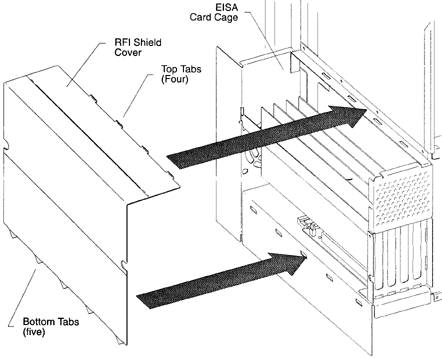
Remove the RFI shield cover by pressing down on the four tabs that fit into the center wall at the top edge of the RFI shield cover, and pulling the shield cover out, as shown below.
Remove the EISA faceplate on the EISA card cage slot where you plan to install the Parallax video card by removing the retaining screw that holds the faceplate to the card edge, as shown below.
Make sure that all unused EISA option slots have a blank faceplate installed and secured with a screw to ensure proper air flow and FCC/Electro-Magnetic Interference emissions compliance.
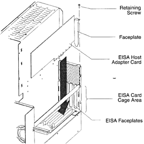
Pick up the Parallax video card, holding it by the edges. Insert the Parallax card into the card cage, as shown above. Slide the card gently but firmly into the EISA connector. Do not force the card because you might damage the connector pins. Check to make sure the card is evenly inserted and seated properly.
Make sure you are grounded to prevent electrostatic damage to the card. Handle the card only by the edges. Do not touch components on the face of the card.
Install the retaining screw, as shown above. Make sure that the retaining screw is fully seated.
Replace the RFI shield cover by inserting the five tabs that fit into the lower part of the card cage and pushing in the four tabs that fit into the top edge of the shield cover, as shown below.
To maintain FCC/Electro-Magnetic Interference compliance, verify that all screws are replaced and firmly seated.
Replace the right-side cover, as shown below.

Replace the top cover and slide it toward the front of the system. Reinstall the thumb screw at the back of the system, as shown below.
Check to make sure the covers and system unit are securely joined and all screws are completely tightened
to maintain FCC/Electro-Magnetic Interference compliance.
Reconnect the cables from your workstation to the monitor, external devices, and network. Reconnect the cables to other EISA cards. Do not turn the power on yet.
Go to Chapter 3 for instructions on connecting cables to your Parallax video card.
Follow these steps to install the Parallax video card into your Model 745 or 747 workstation.
For more details, see your workstation Owner's Guide.
Save your work and shut down the workstation.
Turn off the power to your system (workstation, monitor, and externals).
Disconnect the cables from your workstation to the monitor, external devices, and network. Disconnect cables attached to installed EISA cards.
Use a grounding strap during installation to protect yourself, your workstation, and your video card from electric shocks and damage. (We ship a grounding strap in your hardware package.)
Attach one end of the grounding strap to your wrist. (With the adhesive side to your skin, wrap the grounding strap firmly around your wrist.)

Connect the other end (the copper end) of the grounding strap to any exposed metal casing on the workstation system unit (such as the power supply casing).
If you have an anti-static floor mat, we recommend standing on it during installation.
Remove the SCSI cable from the system module.
Unscrew the captive screws in the EISA module handles (see below) until the screws pop out.
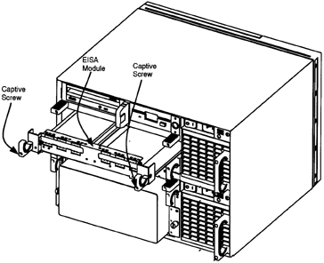
Grasp the EISA module handles and pull the EISA module out of the workstation, as shown above.
Loosen the card clamp captive screw for the appropriate slot, and then remove the card clamp, as shown below.
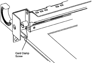
The slots for Model 745i/50 and 745i/100 are numbered from 1 to 4. Cards for slots 1 and 2 are installed component-side up. Cards for slots 3 and 4 are installed component side down.
If your workstation is a 50 Hz or slower 4-slot machine (such as a 745i/50), do not install a Parallax video card in slot 1. Only install your video card/s in slots 2-4.
Remove the slot cover plate by pulling it out of the EISA module.
Make sure that all unused EISA option slots have a blank cover plate installed and secured with a screw to ensure proper air flow and FCC/Electro-Magnetic Interference emissions compliance.
Pick up the Parallax video card, holding it by the edges. Install the Parallax card in the slot (facing up or down as appropriate--see the first note for step 9 above). Slide the card gently but firmly into the EISA connector. Do not force the card because you might damage the connector pins. Check to make sure the card is evenly inserted and seated properly.
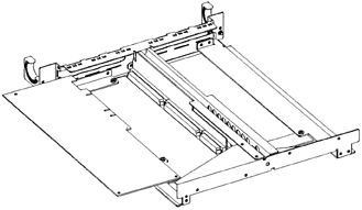
Make sure you are grounded to prevent electrostatic damage to the card. Handle the card only by the edges. Do not touch components on the face of the card.
Replace the EISA card clamp, and then tighten its screw.
Slide the EISA module back into the workstation as shown below, and then tighten the captive screws in the module handles.
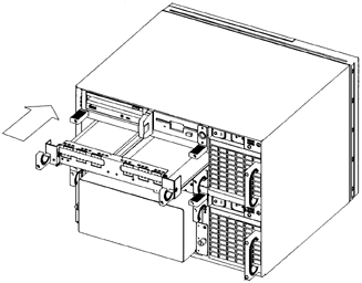
Check that the EISA module and system unit are securely joined and all captive screws are tightened to maintain FCC/Electro-Magnetic Interference compliance.
Replace the SCSI cable on the system module SCSI connector as shown below.

Reconnect the cables from your workstation to the monitor, external devices, and network. Reconnect the cables to other EISA cards. Do not turn the power on yet.
Go to Chapter 3 for instructions on connecting cables to your Parallax video card.
Follow these steps to install the Parallax video card into your Model 735 workstation. For more details, see your HP Owner's Guide.
If your Model 735 system does not have an EISA slot, you need to purchase and install an EISA adapter (EISA expansion slot) before you can install the Parallax video card.
Save your work and shut down the workstation.
Turn off the power to your system (workstation, monitor, and externals).
Disconnect the cables from your workstation to the monitor, external devices, and network. Disconnect cables attached to installed EISA cards.

Use a grounding strap during installation to protect yourself, your workstation, and your video card from electric shocks and damage. (We ship a grounding strap in your hardware package.)
Attach one end of the grounding strap to your wrist. (With the adhesive side to your skin, wrap the grounding strap firmly around your wrist.)
Connect the other end (the copper end) of the grounding strap to any exposed metal casing on the workstation system unit (such as the power supply casing).
If you have an anti-static floor mat, we recommend standing on it during installation.
Remove the power supply cover plate as shown below.
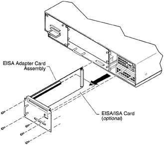
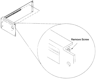
Prepare the EISA adapter to accept the Parallax video card by removing and saving the single screw that secures the blank EISA slot cover in place on the adapter cover plate as shown below. Remove the blank EISA slot cover from the adapter cover plate.
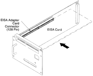
Pick up the Parallax video card, holding it by the edges. Slide the Parallax card gently but firmly into the EISA connector on the EISA adapter assembly, as shown below. Do not force the card because you might damage the connector pins. Check to make sure the card is evenly inserted and seated properly.
Make sure you are grounded to prevent electrostatic damage to the card. Handle the card only by the edges. Do not touch components on the face of the card.
Install the single screw (which you removed in step 7) to secure the EISA card to the adapter card cover plate.
Install the power supply cover plate into the workstation. Screw in the four screws you removed earlier.
Check to make sure the power supply cover plate and workstation are securely joined and all four screws are completely tightened to maintain FCC/Electro-Magnetic Interference compliance.
Reconnect the cables from your workstation to the monitor, external devices, and network. Reconnect the cables to other EISA cards. Do not turn the power on yet.
Go to Chapter 3 for instructions on connecting cables to your Parallax video card.
Follow these steps to install the Parallax video card into your Model 725 workstation. For more details, see your HP Owner's Guide.
You should check the total power requirements of all your EISA option cards before installation to make sure you don't exceed the power limitations of EISA option cards on your Model 725. The Parallax video card uses 27.5 Watts or less (27.5 W for XVideo700, 19.0 W for PowerVideo700 or MultiVideo700) For more information, see your Owner's Guide (Installing and Removing EISA Option Boards).
Save your work and shut down the workstation.
Turn off the power to your system (workstation, monitor, and externals).
Disconnect the cables from your workstation to the monitor, external devices, and network. Disconnect cables attached to installed EISA cards.
If you have the optional external graphics processor, disconnect and remove it. Lift the graphics processor straight up out of the floor stand as shown below.
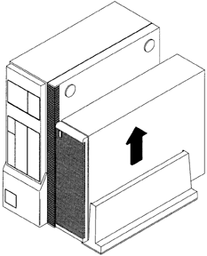
If your workstation is installed in the deskside configuration, lift the system unit straight up out of the floor stand as shown below.
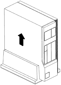
Lay the system unit on a flat surface, such as a table top.
Use a grounding strap during installation to protect yourself, your workstation, and your video card from electric shocks and damage. (We ship a grounding strap in your hardware package.)
Attach one end of the grounding strap to your wrist. (With the adhesive side to your skin, wrap the grounding strap firmly around your wrist.)
Connect the other end (the copper end) of the grounding strap to any exposed metal casing on the workstation system unit (such as the power supply casing).

If you have an anti-static floor mat, we recommend standing on it during installation.
Use the key supplied with your workstation to unlock the cover at the rear of the system unit.
Release the two latches at the rear of each side of the system unit and slide the cover forward an inch or two as shown below.
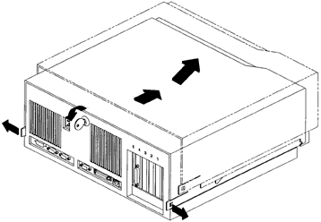
Carefully lift off the cover to fully open the system unit as shown above. Set the cover to one side.
Locate the option slot in which you wish to install the Parallax video card. Remove the screw that secures the blank cover plate for the slot and remove the blank cover plate, as shown below.
If you have an optional CRX graphics card installed in your workstation, you may not install the Parallax card (or any other EISA card) in slot number 4.
If your workstation is a 50 Hz or slower 4-slot machine (such as a 725/50), do not install a Parallax video card in slot 1. Only install your video card/s in slots 2-4.
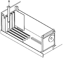
Pick up the Parallax video card, holding it by the edges. Slide the Parallax card partway into the slot, being careful to keep the end of the card aligned with the guide at the front of the system unit, as shown below.
Make sure you are grounded to prevent electrostatic damage to the card. Handle the card only by the edges. Do not touch components on the face of the card.
Align the EISA connector on the Parallax video card with the connector slot on the system board and gently but firmly slide the connector into the slot. Be sure to apply equal pressure on both ends of the Parallax card when inserting it, so that the card seats completely. Do not force the card because you might damage the connector pins. Check to make sure the card is evenly inserted and seated properly.
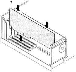
Use the screw that you removed with the blank cover plate to secure the Parallax video card.
Make sure that all unused EISA option slots have a blank cover plate installed and secured with a screw to ensure proper air flow and proper FCC/Electro-Magnetic Interference emissions compliance.
Carefully place the system unit cover back onto the system unit.
Slide the cover back and latch the two latches at the rear of each side of the system unit.
Use your workstation key to lock the cover at the rear of the system unit. Check to make sure the top cover and base of the system unit are securely joined to maintain FCC/Electro-Magnetic Interference compliance.
Do not use the workstation with the top cover removed. The cover is needed for proper air flow for system cooling.
If you want to install your workstation in deskside configuration, lower the system unit onto the floor stand.
If you have an optional external graphics processor, lower it onto the floor stand and re-connect it.
Reconnect the cables from your workstation to the monitor, external devices, and network. Reconnect the cables to other EISA cards. Do not turn the power on yet.
Go to Chapter 3 for instructions on connecting cables to your Parallax video card.
Early Model 715 systems have a slightly different hardware configuration than later 715s. This means the installation procedure is somewhat different for ``Early'' and ``Later'' 715 systems. The installation instructions start out the same (steps 1 through 8), then diverge.
Follow these steps to install the Parallax video card into your Model 715 workstation. For more details, see your HP Owner's Guide.
If your Model 715 system does not have an EISA slot, you need to purchase and install an EISA adapter (EISA expansion slot) before you can install the Parallax video card.
If you have an optional CRX graphics board installed in your system, you may not install an EISA option card such as a Parallax video card.
Save your work and shut down the workstation.
Turn off the power to your system (workstation, monitor, and externals).
Disconnect the cables from your workstation to the monitor, external devices, and network. Disconnect cables attached to installed EISA cards.
If you have the optional graphics processor, disconnect and remove it. If your workstation is installed in the deskside (standing) configuration, remove the graphics processor from the floor stand. Lift the rear of the system unit slightly while sliding the graphics processor back as shown below.
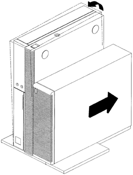
If your workstation is installed in the deskside configuration, remove the floor stand.
Lay the system unit on a flat surface, such as a table top, with the floor stand hanging over the edge.
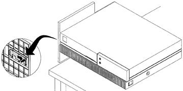
Swing the end of the floor stand away from the system unit and remove it from the system unit, as shown below.
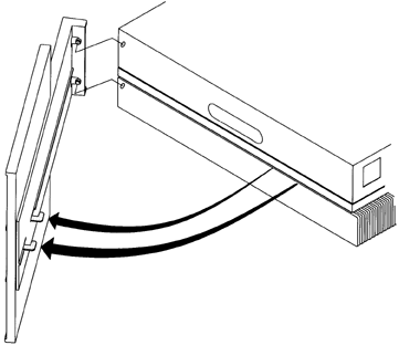
If there is a label covering the handle on the side of the system unit, remove and discard it.
Use a grounding strap during installation to protect yourself, your workstation, and your video card from electric shocks and damage. (We ship a grounding strap in your hardware package.)
Attach one end of the grounding strap to your wrist. (With the adhesive side to your skin, wrap the grounding strap firmly around your wrist.)
If you have an anti-static floor mat, we recommend standing on it during installation.
Later 715 Systems
Continued from step 8
Early Model 715 systems have a handle that pushes in to open the system. Later systems have a handle with a latch that slides to open the system. Determine which type of handle (which type of system) you have.
Slide the system unit's handle latch to the open position (as shown on the handle label) and use both hands to carefully lift the top cover to fully open the system unit. Always lift the system unit cover from the bottom using both hands.
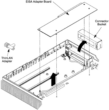
Remove the EISA adapter board, EISA ThinLAN adapter, and connector bucket from the system unit, as shown below.
Some systems have a plastic framework underneath the EISA slot to support EISA cards. The plastic framework has plastic tabs sticking up from it, which prevent the Parallax card from seating correctly. To resolve this problem, cut off the plastic tabs, leaving a flat plastic framework to support the Parallax card.
Remove the EISA filler panel assembly as shown below.
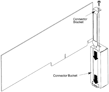
Pick up the Parallax video card, holding it by the edges. Slide the connector bucket onto the Parallax video card's EISA connector bracket as shown below. Insert the tab at the bottom of the connector bracket into the slot on the connector bucket. Then use the screw provided on the bucket to attach the connector bracket.
Make sure you are grounded to prevent electrostatic damage to the card. Handle the card only by the edges. Do not touch components on the face of the card.
Insert the Parallax video card's edge connectors into the connector on the EISA adapter board as shown below. Push gently but firmly to ensure a secure connection. Do not force the card because you might damage the connector pins. Check to make sure the card is evenly inserted and seated properly.
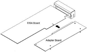
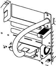
Check that the audio cable is routed as shown below, so it will not be pinched under the Parallax card or the connector bucket.

Slide the connector bucket, which you attached to the Parallax video card, partway into the channels of the connector slot on the rear of the system unit (see below). Align the connector on the adapter board with the connector on the processor board, and carefully press the two connectors together. Ensure that the standoffs are aligned with the standoffs in the CPU board. Press on both the connector bucket and the adapter board to secure the assembly to the system unit.
If you have an optional graphics processor, re-install and
re-connect it, as shown above.
Reconnect the cables from your workstation to the monitor, external devices, and network. Reconnect the cables to other EISA cards. Do not turn the power on yet.
Go to Chapter 3 for instructions on connecting cables to your Parallax video card.
Early 715 Systems
Continued from step 8.
Remove the plastic insert from the system unit handle, if present. Push in the system unit handle and use both hands to carefully lift the top cover to fully open the system unit. Always lift the system unit cover from the bottom using both hands.
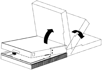
Remove the EISA adapter board, EISA ThinLAN adapter, and connector bucket from the system unit, as shown below.
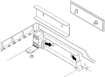
Remove the EISA filler panel assembly as shown below.

Pick up the Parallax video card, holding it by the edges. Slide the connector bucket onto the Parallax card's EISA connector bracket as shown below. Insert the card's connector bracket under the tabs on the face of the connector bucket. Then slide the top of the connector bracket under the tabs on the top of the bucket.
Make sure you are grounded to prevent electrostatic damage to the card. Handle the card only by the edges. Do not touch components on the face of the card.

Insert the Parallax video card's edge connectors into the connector on the EISA adapter board as shown below. Slide the card gently but firmly into the EISA connector, to ensure a secure connection. Do not force the card because you might damage the connector pins. Check to see the card is evenly inserted and seated properly.

Slide the connector bucket, which you attached to the Parallax video card, partway into the channels of the connector slot on the rear of the system unit (see below). Align the connector on the adapter board with the connector on the processor board, and carefully press the two connectors together. Ensure that the standoffs are aligned with the holes in the CPU board. Press on both the connector bucket and the adapter board to secure the assembly to the system unit.
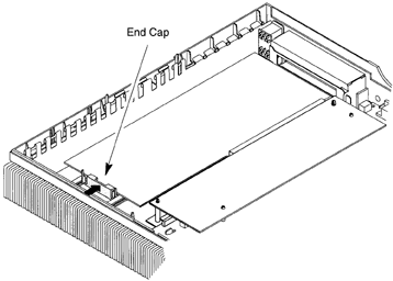
Close the system unit. Always lower the system unit cover using both hands, and holding the bottom of the cover. Use both hands to carefully lower the top cover into place.
Check to make sure the system unit is securely closed
to maintain proper airflow and FCC/Electro-Magnetic Interference compliance.
If you plan to use the workstation in the deskside configuration, re-install the floor stand, as shown below.

If you have an optional graphics processor, re-install and
re-connect it, as shown above. Make sure that the front of the graphics processor is flush with the front of the system unit.
Reconnect the cables from your workstation to the monitor, external devices, and network. Reconnect the cables to other EISA cards. Do not turn the power on yet.
Go to Chapter 3 for instructions on connecting cables to your Parallax video card.
This chapter gives information on the cables included with your video card, how to set up cables for a variety of configurations with video and audio, and how to power up the workstation after installation is complete. This chapter includes:
Cables for Your Video Card
How to Connect the Cables
Basic Set-Up: Video Input
XVideo700: Video Output
Multiple Video Cards in One System
Powering Up the Workstation
Your XVideo700, PowerVideo700, or MultiVideo700 video overlay card comes with a cable and adapters for connecting video devices, and a cable to connect the framebuffer card to the video overlay card to the monitor.

Figure 3-1 The composite/S-VHS (Y/C) video input/output cable (HD26/3DIN-4BNC, part #HP-C-VIO). ``Genlock In'' does not provide Genlock but may provide another Composite video input.

Figure 3-2 We provide two BNC (f) to RCA (m) adapters so that you can connect an RCA video device to a BNC (composite) connector on the cable shown above.
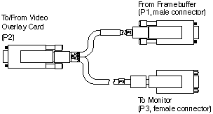
Figure 3-3 The video overlay cable connects the framebuffer to the video overlay card to the monitor cable (HD15/HD15/HD15, part #HP-C-DISP).
XVideo700, PowerVideo700, and MultiVideo700 can be connected to two video sources at once. XVideo700 can display both video inputs simultaneously. PowerVideo700 and MultiVideo700 can display one live video input at a time, with software switching between sources.
Make sure the workstation power is turned off for safety.
Connect the video overlay cable and video input/output cable as shown on the following pages. Connect video sources to connectors labeled ``Video In <Composite or Y/C>'' as appropriate (Y/C is S-VHS). Use BNC to RCA adapters if needed.
A TV cable video source must come through a tuning device (such as a VCR) first so you can select TV channels.
If you have an XVideo700 and want to set up the cables for video output as well as input, see here.
If you have multiple video cards in one workstation, also look here.
Audio input and output is connected through the HP audio system as shown in the examples below. For more information, see your HP Owner's Guide.

Figure 3-4 Parallax Graphics XVideo700, PowerVideo700, or MultiVideo700 card's cable connectors.
Basic cable diagrams for video input follow for these workstations:
J Series
C Series
Model 755
Model 745
Model 735
Model 725
Model 715
If your workstation is not on this list, look for a similar system.
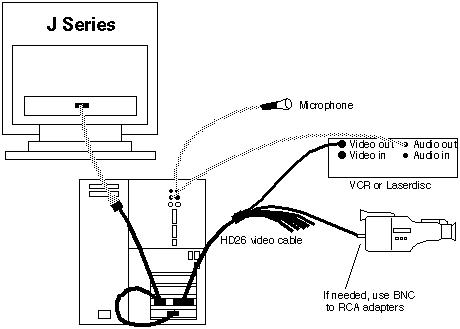
Figure 3-5 J Series workstation: basic connections for an XVideo700, PowerVideo700, or MultiVideo700 card connected to two video sources (and audio). Parallax-supplied cables are shown in black, other cables are grey.
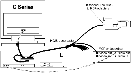
Figure 3-6 C Series workstation: basic connections for an XVideo700, PowerVideo700, or MultiVideo700 card connected to two video sources (and audio). Parallax-supplied cables are shown in black, other cables are grey. Additional audio ports are on the front of the workstation: audio-in (microphone) and audio-out (headphones).
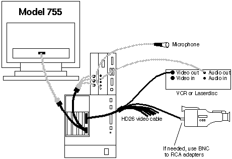
Figure 3-7 Model 755: basic connections for an XVideo700, PowerVideo700, or MultiVideo700 card connected to two video sources (and audio). Parallax-supplied cables are shown in black, other cables are grey.
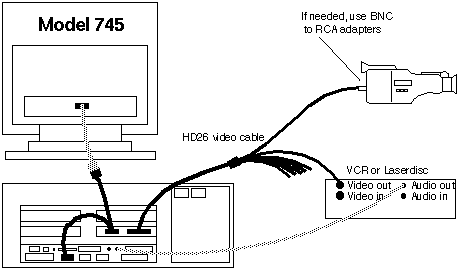
Figure 3-8 Model 745: basic connections for an XVideo700, PowerVideo700, or MultiVideo700 card connected to two video sources (and audio). Parallax-supplied cables are shown in black, other cables are grey. The 745 has only one pair of audio ports.
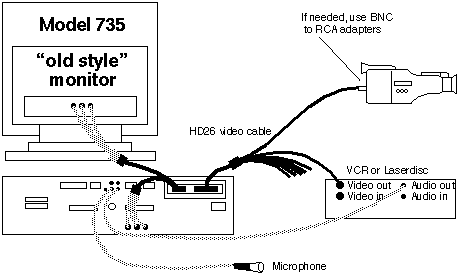
Figure 3-9 Model 735 (shown with an ``old style'' monitor with separate RGB connectors): basic connections for an XVideo700, PowerVideo700, or MultiVideo700 card connected to two video sources (and audio). Parallax-supplied cables are shown in black, other cables are grey.
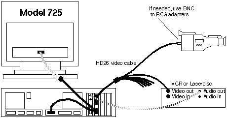
Figure 3-10 Model 725: basic connections for an XVideo700, PowerVideo700, or MultiVideo700 card connected to two video sources (and audio). Parallax-supplied cables are shown in black, other cables are grey. Additional audio ports are on the front of the work-station: audio-in (microphone) and audio-out (headphones).
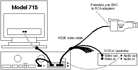
Figure 3-11 Model 715: basic connections for an XVideo700, PowerVideo700, or MultiVideo700 card connected to two video sources (and audio). Parallax-supplied cables are shown in black, other cables are grey. Additional audio ports are on the front of the work-station: audio-in (microphone) and audio-out (headphones).
XVideo700 can also display one live video and send video out to an external device such as a VCR, laserdisc recorder, TV monitor, or video projector. The video for output may come from live video, pre-recorded MovieTool movies, VideoTool-displayed still images, and possibly from independent software vendor applications. See your Multimedia User's Guide for details.
To use video output, connect one of the XVideo700 video output connectors (``Composite Out'' or ``Y/C (S-VHS) Out'') to a video input connector on the external video device.
To use audio output, connect the HP audio output to an audio input connector on the external video device.
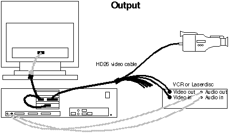
Figure 3-12 Video output connections for XVideo700. Output can be used while displaying one live video input (and while showing captured still images and playing back digital video movies). Video input in this diagram could be from either the camera or the VCR/Laserdisc. Video output is to the VCR/Laserdisc Recorder. Audio input in this diagram is from the VCR/Laserdisc (or from a microphone connected to the front), and output is to the VCR/Laserdisc Recorder. Parallax-supplied cables are shown in black, other cables are grey.
Set up the cables so that the Parallax Graphics video overlay cables are linked to connect the framebuffer to the series of video overlay cards to the monitor cable. The order of the video cards is not important.
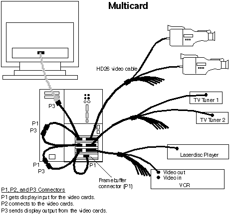
Figure 3-13 Setting up cables for two or three video cards in an HP work-station. All cards can see and switch between two video sources; only XVideo700 cards can display two inputs at once. XVideo700 can also send output to external devices . Parallax-supplied cables are shown in black, other cables are grey.
The sequence of the video overlay cards is not important. You can connect the framebuffer (first P1 connector) to the video cards - in any sequence - to the monitor cable (last P3).
For multiple video cards, also look at the special set-up instructions in your Software Installation Guide.
If you installed the Parallax Graphics video card into a new workstation that has never been powered up, you'll need to refer to your workstation user's guide for special power-up (and, if applicable, networking) instructions.
If you installed the video card into a workstation that has previously been powered up, turn the power back on by turning on the switches you turned off before installation, in the following order:
Turn on your monitor.
Turn on any external drive units. (If you have more than one drive connected, and if these are daisy-chained, power-on the most remote drive first, then the next most, etc.)
Turn on your workstation.
When the login prompt appears on the host command line, you can start the software installation instructions in your Software Installation Guide.
This appendix covers the specifications of Parallax Graphics XVideo700, PowerVideo700, and MultiVideo700. Appendix A includes:
General Specifications
System Requirements
Video Architecture
Software Support
Video Performance
Display
Environment
Interoperability
Warranty
Specific Video Overlay Cards
XVideo700
PowerVideo700>
MultiVideo700
Platform *HP Apollo 9000 Series 700, B, C, and J Classes
EISA Bus Interface One available EISA Bus slot
Operating System HP-UX 9.03, 9.05, 9.07, 10.10, or 10.20
Window Environment HP VUE 2.0 or higher or CDE
Available Disk Space 35 Megabytes (MB) space on a local hard drive(20 MB for Parallax version 9.2)
System RAM 64 MB recommended (32 MB minimum)
Swap Space 64 MB recommended (32 MB minimum)(MultiVideo700 needs just 32 MB recommended)
Framebuffer Types *HCRX 24, Visualize 24, Visualize 48
Monitor Types *1280 x 1024 pixels @ 60-75 Hz
*1024 x 768 pixels @ 60-75 Hz
*NOTE: Not all systems work at all display resolutions. See Release Notes for details on tested systems.
NOTE: The hardware supports displays at 1280 x 1024 or 1024 x 768 pixels at frequencies between 60-75 Hz (theoretically up to 76 Hz). Calibration files support several specific display types (1280 x 1024 @ 72 and 60 Hz, 1024 x 768 @ 75 and 74 Hz), and can be adjusted to meet other frequencies between 60-75 Hz. For details, see your Release Notes and Software Installation Guide instructions for Calibrating and using Calibrate with the ``-hv'' option (Troubleshooting).
Architecture Video overlay card (up to 1280 x 1024 x 28 bits)
Applications VideoTool for live video display and still image capture
MovieTool for motion video capture and playback
Developer Tools Video Development Environment includes API, libraries, widgets, and sample source code and programs
Driver Device driver for HP-UX
NTSC 640 x 480 pixels @ 60 fields (30 frames)/second (525 line)
PAL or SECAM 768 x 576 pixels @ 50 fields (25 frames)/second (625 line)
Sampling Frequency Square pixels;
525 line: 12.2727 MHz;
625 line: 14.75 MHz
Placement Arbitrary placement on screen;
Realtime image sizing (reduce in, expand out);
Switch video on a pixel-by-pixel basis
Clipping/Stenciling Pixel-by-pixel masking of live video
Pixel Replication Hardware enabled zoom at 1x and 2x (2x width/height, 4x area) for one live video window
Color Mode 24-bit RGB video
Power Requirements 5.5 Amps @ +5VDC \xb1 5%
0.02 Amps @ -5VDC \xb1 10%
0.18 Amps @ +12VDC \xb1 10%
0.012 Amps @ -12VDC \xb1 10%
(PowerVideo700 and MultiVideo700 require slightly less power.)
Operating Temperature 10-50\xb0 C (50-120\xb0 F)
Cross-Platform Support Interoperable with Parallax Graphics SBus/Solaris video framebuffer and overlay cards and software.
Hardware Warranty One year limited hardware warranty (see Appendix B). Extensions to warranty available.
Video Display Up to two simultaneous live video windows from two
composite or one composite plus one S-VHS (Y/C)
analog inputs
Video Input Formats NTSC, PAL, SECAM as composite or S-VHS (Y/C),
software selectable
Video Output Formats NTSC, PAL as composite or S-VHS (Y/C)
Compression Hardware accelerated JPEG compression and decompression for real-time motion video and still image
capture and playback. Compression ratios range from 20:1 to 100:1.
Video Overlay Cable HD15 to HD15 to HD15 Y cable
Video Input/Output Cable HD26 to 3 DIN and 4 BNC cable
Video Display One live video window from composite or S-VHS (Y/C) analog inputs
Video Input Formats NTSC, PAL, SECAM as composite or S-VHS (Y/C),
software selectable
Compression Hardware accelerated JPEG compression and decompression for real-time motion video and still image
capture and playback.
Video Overlay Cable HD15 to HD15 to HD15 Y cable
Video Input/Output Cable HD26 to 3 DIN and 4 BNC cable
Video Display One live video window from composite or S-VHS (Y/C) analog inputs
Video Input Formats NTSC, PAL, SECAM as composite or S-VHS (Y/C),
software selectable
Video Overlay Cable HD15 to HD15 to HD15 Y cable
Video Input/Output Cable HD26 to 3 DIN and 4 BNC cable
All Parallax Graphics video cards come with a 1-year hardware warranty (1-year extensions to the warranty are available). This appendix includes:
Hardware Warranty
If You Need a Repair
Parallax Graphics hardware products are guaranteed to be free from manufacturing defects for one year from date of shipment.
All warranty repair work is FOB (``freight-on-board'') Parallax Graphics, Santa Clara, California (USA) and includes parts and labor and return shipment to Parallax's customer. Expedited return shipments are available at additional cost.
This warranty does not cover gross neglect, physical damage, or use outside of published operating limits, nor does it cover software or firmware.
A factory repair service is also available for out-of-warranty hardware.
To speed up the repair process, please call us at +1 703 715 3017 and ask for technical support. Tell us what the problem is and ask for an RMA (``return material authorization'') number. Then ship the video card to Parallax for repair and include the RMA number with the shipment.
- You will pay for shipping the video card to Parallax Graphics for repair. Parallax is not liable for damage that occurs during shipment, so you may want to insure the shipment.
To prevent disruption of radio frequency communications such as ambulance, police, and air traffic control, the USA Federal Communications Commission (FCC) and European Union have established rules limiting radio frequency interference generated by equipment such as computers and video cards. This appendix briefly describes the regulatory compliance and requirements.
Preventing Radio Interference: Your Responsibility
Avoiding Penalties in the USA
FCC Class A Notice
This video card and cables have been tested and comply with FCC (Part 15, Class A devices) and European (CE Mark: EN50081-1 [EN55022], EN50082-1) standards. The cables are required to comply with these standards. If you use this equipment in the USA or Europe, you are responsible to ensure continued compliance as follows:
You must install and use this video card and cables as described in the manuals.
You must use the video card with the cables provided.
You must not make any changes or modifications to the video card and cables.
In the USA, you must use the video card and cables in a commercial zone.
If you do not follow the four guidelines above (for instance, if you use the equipment in a residential zone in the USA), you may cause disruptive radio frequency interference. If that happens in the USA, you may have to stop using the equipment until you correct the radio interference problem at your own expense.
This device complies with part 15 of the FCC Rules. Operation is subject
to the following two conditions: (1) This device may not cause harmful interference, and (2) this device must accept any interference received, including interference that may cause undesired operation.


